EXAMPLES
Overview
The following examples illustrate the various ways in which you can use sub-circuits and multi-sheet designs to split your project into logical blocks. There are also examples of how to re-use these blocks in the same design and also across different Proteus projects.
Example: Simple Sub-Circuits
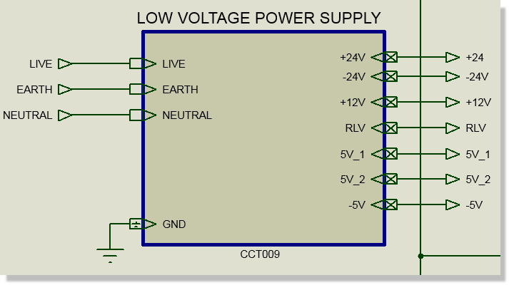
An example of a logical block encapsulated in a sub-circuit.
Here we have added a sub-circuit on the parent sheet of the schematic and then added and named the ports on the sub-circuit body. We've connected all the ports to input or output terminals and given everything a sensible name. This is all covered previously in the basics of sub-circuits.
The next step is to right click on the sub-circuit, enter the child sheet and then design a block of circuitry that performs the logical function of the sub-circuit. The key thing to remember is that you 'join up' the signals on the child sheet to the ports on the sub-circuit by naming the terminals with the port names.
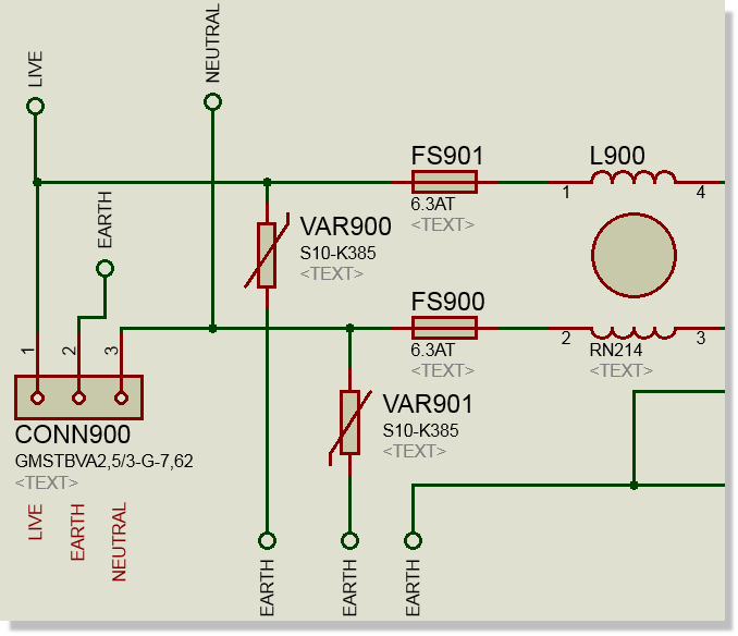
Terminal names matching the names on the ports transfer connections up and down the design hierarchy.
Key Concept : Scope
Everything connected inside a sub-circuit is local to that sub-circuit with the exception of nets of type POWER.
A power net is denoted by the use of a terminal of type POWER or GND. Nets with the names VCC and GND are always of type POWER.
Power nets are default design global so that you don't have to wire up and down through lots of sub-circuits.
As an example, the terminals above are all local and are wired up through the sub-circuit ports into the parent sheet. The terminals below are design global (using POWER terminals).
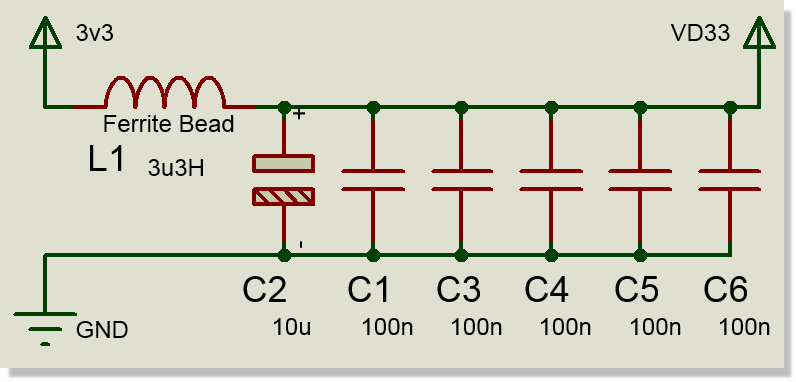
Power terminals default to being design global
If you want to use power terminals but still wire everything up between sub-circuits then you can un-tick the Global Power Nets? option on the Edit Design Properties command, which is on the Design menu.
Rules of Thumb
If a block of circuitry does a single job, it's best in a sub-circuit.
Decide early how you want to handle power nets for your project. You can either have them all global to the design or you can have them local to a sheet. If you want global power nets (convenience) then use power terminals. If you want them local (explicit wiring) then either use default terminal types or un-tick the Global Power Nets? option.
To connect from the sub-circuit to the parent sheet wire to a terminal and give the terminal the same name as the port on the parent sheet.
Example: Single Sheet Annotation
One of the nicer properties of a sheet is that it can contain an annotation base. This allows you to separate the annotation of parts contained in one sheet from that on a second sheet. The process is simple.
- Place the sub-circuit, attach and name the ports in the usual way.
- Enter the sub-circuit and then invoke Design Menu > Edit Sheet Properties.
- Change the Annotator Init field for the sub-circuit, for example to 500.
- Place and wire circuitry in the usual way.
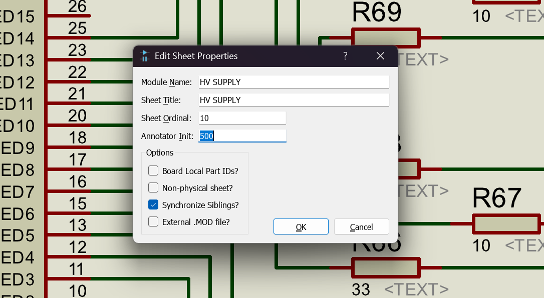
Initial annotation set to 500 sets an annotation base for components placed on that sheet.
If you have placed components and then decide that you want a base annotation for the sheet later, run the Global Annotator with its Scope set to Current Sheet and enter the value you want in the Initial Count field.
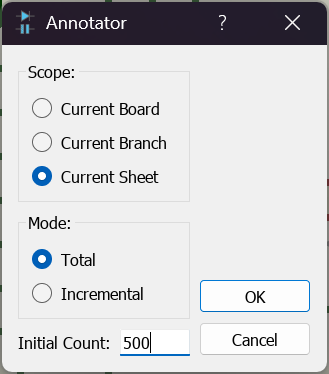
The Global Annotator set to Current Sheet scope and Total mode.
Note that sub-circuit annotation will typically not survive re-annotation from the layout. The layout module has a command for annotating the board in a physical way, for example top left to bottom right, and this will re-annotate the schematic automatically. You can choose to have the logical annotation preserved by ticking the Use sheet offsets checkbox on the Global Part Annotator, which is the Automatic Annotator command on the Tools menu of the layout module.
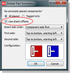
Use sheet offsets in the layout annotator maintains the schematic annotation at the expense of directional flow on the physical layout
Example: Multi-Sheet Annotation
The Global Annotator is used to batch annotate designs, but it can also be used to annotate only a branch of a design. A branch of the design is considered to be the current sheet downwards in the hierarchy.
Re-annotating with the Scope set to Current Branch will:
- Set the initial count of the current sheet to the annotation specified on the dialogue form.
- Annotate the current sheet and then propagate downwards through any child sheets.
- Preserve any initial annotation counts specified in child sheets.
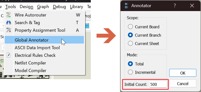
Current Branch scope with Total mode annotates downwards through the hierarchy.
This mode is ideally suited to re-annotating after a copy and paste of a sub-circuit hierarchy.
Example: Duplicating Circuitry (Project Clips)
- ✗ Not suitable for duplicating sub-circuits that themselves contain sub-circuits: project clips are single sheet only.
- ✓ Suitable for re-use between projects.
- ✓ Simple and easy to use.
Step 1: Create Project Clip
Create the Project Clip and store to disk.
Step 2: Set up Sub-Circuits
Place a sub-circuit, along with its ports, and then name the Sheet and Circuit appropriately.
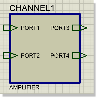
A sub-circuit with the sheet named CHANNEL1 and the circuit named AMPLIFIER.
Select and block copy the sub-circuit as many times as you need and then rename the sheets. Do not rename the circuit, as this is the binding.
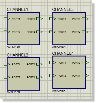
Four copies of the sub-circuit, each with its own sheet name but all bound to the same circuit.
Step 3 : Import the Project Clip
Enter the first sub-circuit (CHANNEL1 in our example) and import the Project Clip. This will populate and correctly annotate all of the other sub-circuit channels as well.
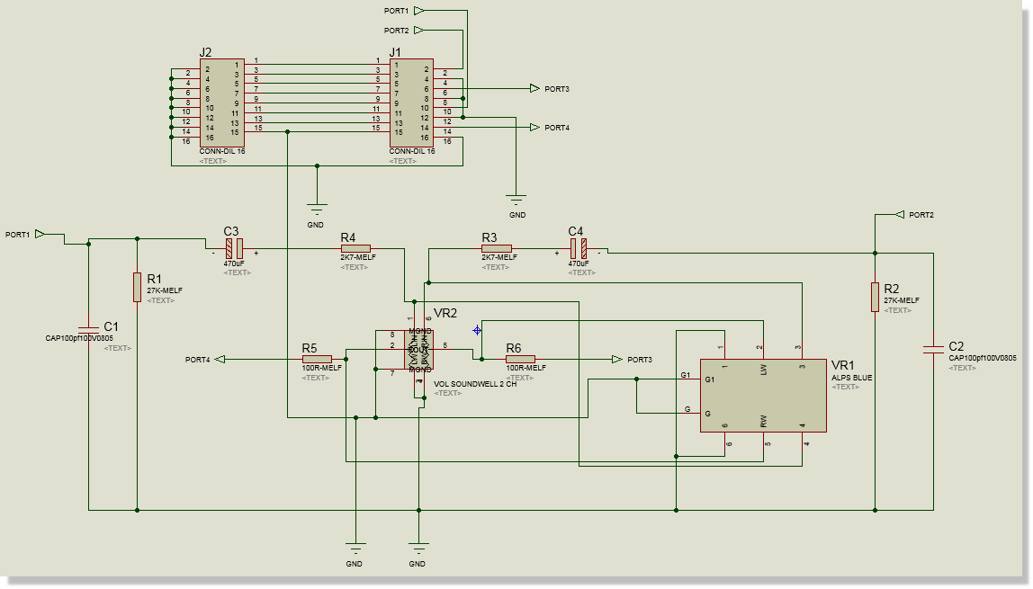
The imported clip populates the child sheet of every sub-circuit bound to the same circuit.
Step 4: Place the layout clips
On the layout side, you will have five clips in the parts bin, each of which will place as a single entity with the correct annotation.
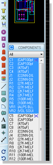
Each imported clip arrives in the layout parts bin as a single annotated block.
If you decide to add another channel (e.g. CHANNEL6) once the project clip has been imported you will need to place the sub-circuit and import the project clip into it manually. It's best to set up all the empty sub-circuits with the same name and then import the project clip into one of them.
If you haven't set a sheet annotation offset and then decide you want one later, you can use the annotator in the layout module or run the Global Annotator with its Scope set to Current Branch, as described above.
Example: Duplicating Circuitry (Replicate)
- ✓ Suitable for duplicating sub-circuits that themselves contain sub-circuits, which is to say a multi-level hierarchy.
- ✗ Not suitable for re-use between projects.
The following process shows how to duplicate circuitry inside a project.
Step 1: Lay out the first schematic sub-circuit
Place the first sub-circuit and lay out the circuitry. Edit the circuit name and sheet name to reflect the contents of the sub-circuit.
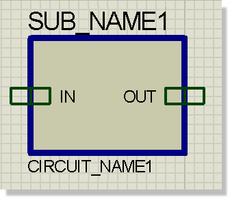
The first sub-circuit, with its sheet name and circuit name both set.
The circuit inside SUB_NAME1 also contains a sub-circuit, which in turn contains another circuit:
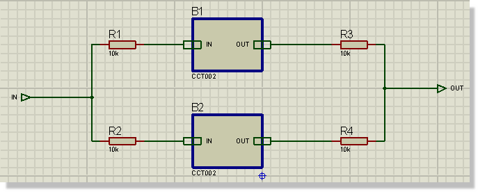
The child sheet itself contains further sub-circuits, giving a multi-level hierarchy.
Step 2 : Copy and Paste
Block copy the sub-circuit on the root sheet (the top level of the hierarchy branch) as many times as required and rename the sheet. Do not rename the circuit, as this is the binding.
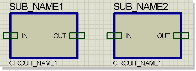
The copy takes a new sheet name but keeps the original circuit name.
The two sheets now contain the same circuit. Making a change to one will also make the same change in the other one.
Step 3: Re-Annotate the Copies
Note that at this stage you will have duplicate annotations in the various sheets. Run the Global Annotator with its Scope set to Current Board to generate unique annotations for all of the copies. If you prefer, you can enter each circuit in turn and work with the Scope set to Current Branch and a different Initial Count for each. This will set sheet annotation for you.
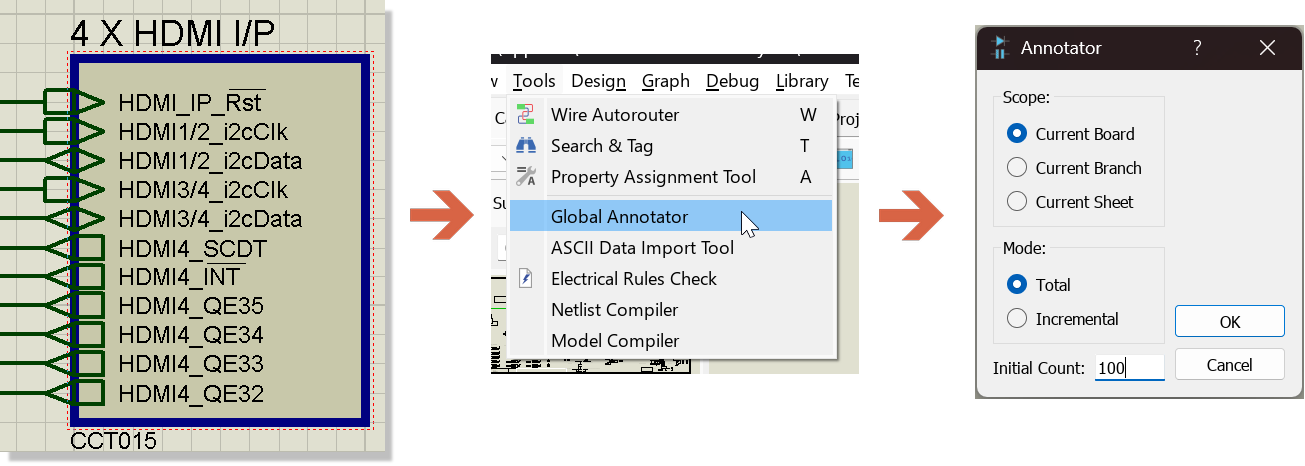
Annotating the whole board in Total mode gives every copy its own set of references.
OR
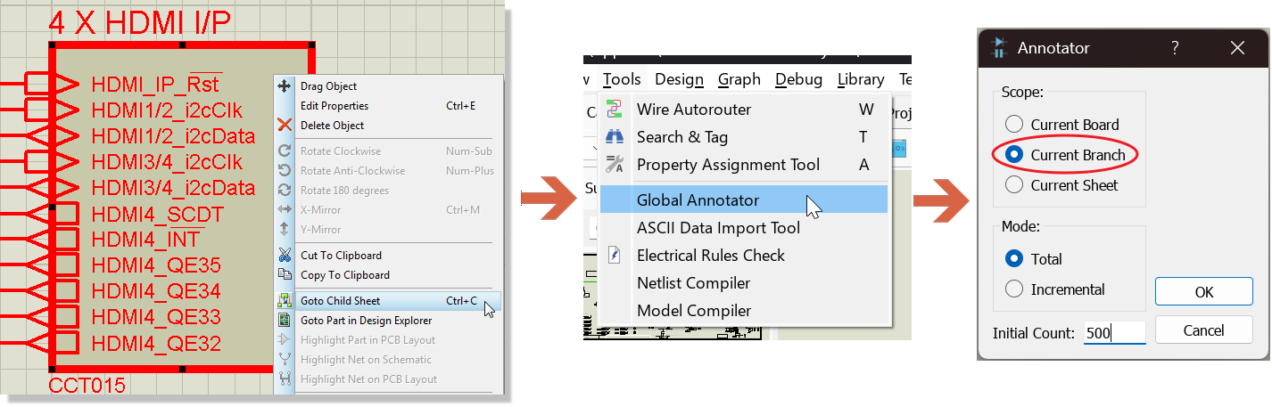
Entering each branch in turn and annotating it with its own initial count.
See Also
Step 4: Layout one Circuit
Place and track the first section of circuitry in the layout module. It's easiest if you do this in open space for now so that you can easily select it.
Step 5 : Replicate the other Copies
Carefully draw a selection box around the circuitry and invoke the Replicate command on the layout module's Edit menu. If the Bind To selector on the Replicate form is disabled, you have selected parts not contained in the sub-circuit. Select the second sheet to bind to, and an X-Y offset for the placement.
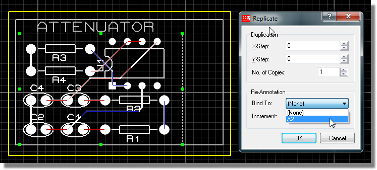
The Bind To selector on the Replicate form names the sheet the copy is annotated against.